Objective
Water Pump Bearing Vibration Analysis system was developed to modify
design and develop “On Line Noise/Vibration Testing Unit”.
Test Requirements
- Design Test System
where different types of Bearings Manufacturing Unit can be tested
in production line.
Test System Capabilities
- The test system
will be used for on line testing each bearing for the following
parameters.
- Characteristic
Frequency & Order measurement for both bearing constant and
variable speed (RPM).
- Fundamental Train Order / Freq
- Ball Spin order / Freq
- Outer race order / Freq
- Inner race order / Freq
- Orbit Plot of
shaft – to indicate the clearances. The above definitions and
technical meaning will be explained to you with their significance
during the project execution. We will ensure your understanding on
the subject.
- Power spectrum (X
& Y axis) over operating rpm range vs Freq.
- Spectrum envelope
generation with tolerance band for good bearing.
- Statistical
analysis for parameters like:
- Max & Min values (
Accl, Vel & Displ )
- Std deviation for each
( Accl, Velo & displ )
- Kurtosis
- Any other basic
analysis as relevant.
- Off Line bearing
fault analysis tools for typical bearing defects.
- The typical cycle
time will be 12 secs max per piece. Please note the above cycle
time is arrived based on assumption. Actual cycle time we need to
arrive during trials with system and samples.
- The Test System
will be robust and designed to accommodate different bearing
assemblies based on specs given above.
- The system shall
show Green & Red signals for OK & NOT OK bearings
respectively.
- The system will
also have buzzer for not OK bearing along with Red indication on
LCD Panel.
- This will also
have the calibration system with master bearings for all
measurements.
- Also provision of
noise data to be filtered in following frequencies:
- Low Band – 50 ~ 300
Hz-OK
- Medium Band – 300~1800
Hz-OK
- High Band – 1800~ 10000
Hz
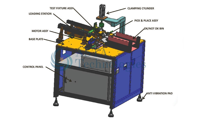
Technical Description
- Bearings are
loaded on chute by manually and they roll down in chute by
gravitational force.
- Indexing
V-block with pneumatic cylinders:- Indexing v-block is
proposed for transferring the bearing from chute to Test Station.
- Testing:-
After Placing of bearing at test block, upper holding block will
come and hold the bearing having accelerometer in X direction. Then
Magnetic coupling will actuate forward and to be grip the bearing
shaft, then after test will be start for 5 Sec, max. Rpm would be
3000 max. As discussed with you, run-out of coupler after mounting
on shaft should be max 0.05mm. Also movement of chuck should be
free.- But the run-out value may change up to 0.1 mm.
- In the holding
condition, we can change the clamping load by the pressure change
of Cyl.
- Vibration probe
mounted with radial load system will measure vibrations and data
will be forwarded to DAQ system for processing. (Measurement
unit of vibration is g/mm per sec.)
- To hold the
bearing sleeve there will be proper support for both ends.
- After the testing,
there is a manipulator that is having pneumatic centric gripper
with rotary and Z axis Actuator for Placing the Bearing in the Bin.
- If bearing is ok
then manipulator place the bearing on ok conveyor and if the
bearing is not ok, flap will actuate for not ok bin which is placed
below conveyor.
- We are considering
the cycle time would be 12 max Sec.
- Whether the
vibration results (Peak to Peak / RMS) will be based on
acceleration and displacement.
- This will also
have the calibration system with master bearings for all
measurements.
- "Time series plot
for acceleration, velocity & displacement" or " 1/3 Octave
analysis & Plot" or "Spectrum plots & analysis.
- This will also
have the calibration system with master bearings for all
measurements.
- The methodology to
adjust the pressure of vibration sensor on the outer diameter of
bearing.
- For NOT OK
bearings, we need buzzer along with red indication on LCD panel, We
need counter for the measurement of output of ok bearings & its
linkage to PC.
- We need linkage of
rejected bearings to the rejection bin so as to ensure that if the
rejected bearing doesn't reach rejection bin, next operation will
not be started.
- The equipment
should have calibration system with master bearings.
- UPS and Control
Panel would be mounted under the table top.
- To avoid a
vibration of mechanical system (servo motor, drive etc.) we are
using magnetic chuck between motor drive and pneumatic chuck. Function:-
Servo motor (Panasonic make) will give the drive to magnetic chuck
& magnetic chuck will give the drive to pneumatic chuck without any
mechanical attachment, so that gripper will rotate the bearing
without any mechanical vibration.-Ok
- Machine will be
supplied with anti vibration pads.